Blog

Get the latest insights or read more about a specific topic.

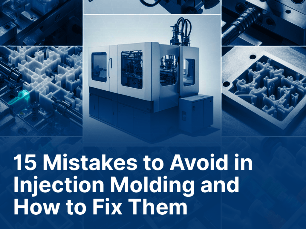
15 Mistakes to Avoid in Injection Molding and How to Fix Them?

fixing injection molding mistakes

Designing injection molding parts involves a multi-step process that requires careful consideration of various factors. Injection molding is a widely used manufacturing process for producing plastic parts and components, ranging from everyday consumer products to complex automotive and medical devices.

Designing parts for injection molding requires a deep understanding of the process, materials, and the specific demands of the end product. Mistakes in the design phase can lead to various issues, including defects, high production costs, and delays in manufacturing. Hence, engineers and designers in this field aim to create designs that not only meet functional requirements but also optimise the injection molding process for efficiency and quality.

Importance of Designing Injection Molding Parts

Designing injection molding parts is crucial for several reasons like:

  1. Quality Assurance: Proper design reduces the likelihood of defects, ensuring consistent, high-quality parts.
  2. Cost Efficiency: Effective part designs can reduce material wastage and shorten production cycle times, resulting in cost-effective benefits.
  3. Consistency: Consistent designs facilitate reproducible manufacturing processes, reducing variations in product quality.
  4. Durability: A well-executed design guarantees the part’s resilience against environmental factors and the effects of wear and tear.
  5. Functionality: Good design ensures that the part functions as intended, meeting performance and requirements.
  6. Material Selection: Design impacts material selection, allowing for the use of materials that meet specific criteria like durability, flexibility, or chemical resistance.
  7. Manufacturability: A well-designed part is easier to mold, reducing the risk of manufacturing issues and delays.
  8. Faster Time to Market: Streamlined design practices help minimize scrap and waste, aligning with sustainability objectives.
  9. Cost Reduction: Optimised designs can lower tooling and production costs, enhancing competitiveness.
  10. Waste Reduction: Efficient design minimises scrap and waste, contributing to sustainability goals.

15 Mistakes to Avoid while Manufacturing Injection Molding Parts

The design of molded products involves creating 3D shapes or components using an injection molding process. Molded designs require careful consideration of various factors, like material selection, geometry, and the mold itself. The goal is to create designs that are not only functional but also optimised for the molding process, leading to high-quality finished products. If not, these mistakes can lead to issues like structural weaknesses, defects, increased production costs, and delays. 

By avoiding these common mistakes, designers can save time, reduce production costs, and improve the overall quality of molding parts. Explore our in-depth guide on designing injection molding parts without common pitfalls. Learn from our expert advice on avoiding mistakes to enhance part quality and streamline manufacturing. Following are the 15 mistakes that must be avoided while designing injection molding parts.

  1. Underestimating Material Selection:
    • Selecting the wrong material for your application can lead to issues like poor durability, warping, or colour inconsistencies. 
    • Underestimating material selection in the design of injection molded parts can result in a cascade of problems that affect the part’s performance, appearance, cost-efficiency, and sustainability. 
    • Therefore, thorough research and consideration of material properties and characteristics are essential to make informed design decisions. Choose a material suitable for your part’s intended use.
  1. Neglecting Material Shrinkage:
    • Different materials have varying shrinkage rates during cooling. 
    • Account for this shrinkage in your design to prevent size and fit issues in the final product. 
    • (Material shrinkage in injection molding is the reduction in size or volume of the molten plastic material as it cools and solidifies inside the mold, affecting the final part dimensions)
  1. Inadequate Wall Thickness:
    • Inadequate wall thickness in injection molding parts can lead to structural weaknesses, warping, and inconsistent quality. 
    • Insufficient material thickness may compromise the part’s ability to withstand mechanical stresses and environmental factors. 
    • It can also result in sink marks or deformities due to uneven cooling. 
    • Properly assessing and maintaining uniform wall thickness in the design is essential for ensuring the durability, functionality, and overall quality of the final product. 
    • Ensure uniform thickness and use design guidelines provided by material suppliers.
  1. Inconsistent Wall Thickness:
    • Avoid abrupt transitions in wall thickness, as these can cause flow irregularities during molding. 
    • Gradually taper changes in thickness to improve material flow.
  1. Sharp Corners and Edges:
    • Sharp corners can result in stress concentrations, which may cause part failure or create weak points. 
    • Use fillets and radii to distribute stress more evenly.
  1. Ignoring Draft Angles:
    • Ignoring draft angles in the design of injection molded parts can lead to numerous manufacturing and quality issues. 
    • Draft angles are essential because they facilitate the ejection of the part from the mold. 
    • Without adequate draft angles, parts can become stuck in the mold, leading to production delays and potential damage to the tooling. 
    • Furthermore, the absence of draft angles can result in surface imperfections, such as scuffs and scratches, as the part drags against the mold during ejection. 
    • Additionally, it may cause warping or distortion of the part due to the forces applied during removal. Thus, overlooking draft angles can significantly impact production efficiency, tool longevity, and the overall quality of the molded parts. 
    • (What are Draft Angles? raft angles are slight tapers added to vertical surfaces in molding to aid in part ejection. They prevent sticking, surface damage, and help maintain mold longevity.)
  1. Overlooking Ribs and Bosses:
    • Inadequate support structures like ribs or bosses can cause sink marks, warping, or uneven cooling. 
    • Design these features carefully to enhance part strength and performance. 
    • (Ribs and bosses are structural features in injection-molded parts. Ribs add strength and stiffness, while bosses serve as attachment points. Both elements are strategically designed to enhance a part’s performance and functionality.)
  1. Complex Geometrics:
    • Complex geometries in injection-molded parts refer to intricate shapes, curves, or structures that can be challenging to manufacture. 
    • These designs often require advanced tooling and can increase production costs. 
    • Engineers strive to balance complexity with manufacturability, aiming to create parts that meet performance requirements while minimising production challenges and costs. 
    • Simplify designs when possible without compromising functionality.
  1. Neglecting Gate Placement:
    • Gate placement affects the flow of material and can lead to cosmetic defects. 
    • Optimise gate location to minimise visible marks on the finished part. 
    • (Gate placement in injection molding is where molten plastic enters the mold. It impacts material flow, part quality, and mold complexity, making it crucial for efficient and high-quality production.)
  1. Not considering Tolerances:
    • Overly tight tolerances can be costly and difficult to achieve in molding. 
    • Ensure tolerances are realistic and necessary for part’s function.
  1. Ignoring Simulation Tools:
    • Ignoring simulation tools in injection molding design is a mistake that can lead to costly issues. 
    • These tools predict material flow, cooling rates, and potential defects. 
    • Failure to use them can result in design flaws, such as improper gating or cooling, which may only become apparent during production, leading to increased expenses, longer lead times, and reduced product quality. 
    • Simulation tools help optimise designs and prevent these problems. (Few simulation tools: Moldflow, SolidWords Plastics, Moldex3D, COMSOL Multuphysics, etc.)
  1. Skipping Prototyping and testing:
    • Rushing into production without prototyping can lead to costly design errors. 
    • Prototyping and testing help identify and address issues early in the process.
  1. Inadequate Venting and Cooling:
    • Poor venting can result in trapped air or gases, causing defects. Ensure proper venting and cooling channels to maintain part quality.
  1. Complex Ejector Systems:
    • Overly complex ejector systems can increase mold complexity and cost. 
    • Keep the ejection system as simple and efficient as possible.
  1. Lack of Communication with Mold Maker:
    • Maintain clear and open communication with the mold maker to ensure the mold is built according to your design specifications.

By avoiding these common mistakes when designing injection molded parts, you can enhance the efficiency, quality, and cost-effectiveness of the manufacturing process. Collaboration between designers, engineers, and mold makers is essential to achieve optimal results

Fixing Injection Molding Mistakes: A Top-Down Approach

The detailed table stating injection molding mistakes, causes, consequences, and solutions is given below:

MistakesCauseConsequenceSolution/ Precaution
Underestimating Material SelectionLack of expertise in material properties or an inadequate evaluation of material requirements.Poor part performance, material incompatibility, and potential safety issues. Thoroughly research and select the right material for the specific application and environment conditions. 
Neglecting Material ShrinkageFailure to account for material shrinkage during design.Deviations from desired part dimensions, fitment issues, and potential product failure. Account for the expected material shrinkage during design phase by adjusting dimensions accordingly, ensuring the final part matches the intended specifications. 
Inadequate Wall ThicknessLack of awareness of material-specific wall thickness requirements or cost-cutting efforts.Structural weakness, warping and sink marks in part.Ensure uniform wall thickness throughout design, follow material specific guidelines.
Inconsistent Wall ThicknessLack of attention to maintaining uniform thickness in design.Structural weaknesses, warping sink marks, and uneven cooling Add fillets or radii to corners and edges to distribute stress evenly and prevent structural weaknesses and cosmetic imperfections. 
Sharp Corners and Edges Oversight of the need for fillets or radii.Stress concentration, potential part failure, and cosmetic defects. Add fillets or radii to corners and edges to distribute stress evenly and prevent structural weaknesses and cosmetic imperfections. 
Ignoring Draft AnglesRushing the design phase or overlooking the importance of draft angles.Difficulty in part ejection, potential damage to the mold, and surface defects. Incorporate appropriate draft angles to facilitate smooth ejection and reduce friction. 
Overlooking Ribs and BossesInsufficient consideration of material flow or cosmetic requirements during design.Weakness in the part, potential warping, cooling irregularities. Carefully design ribs for added strength and bosses for fastening points, ensuring they enhance the part’s performance without causing production issues. 
Complex GeometriesPursuit of intricate designs without considering their manufacturability.Increased tooling and production costs, longer lead times, and manufacturing challenges.Simplify designs when possible without compromising functionality or performance.
Neglecting Gate PlacementInsufficient consideration of material flow or cosmetic requirements during design.Visible gate marks on the part, uneven material flow, and cosmetic defects.Carefully select gate locations based on part design, material, and cosmetic requirements. 
Not considering TolerancesUnrealistic expectations or an excessive focus on precision.Difficult and expensive manufacturing, potential issues with part assembly.Specify tolerances that are realistic and necessary for the part’s function.
Ignoring Simulation ToolsUnawareness of simulation benefits, cost considerations, or resistance to change.Potential defects, production delays, increased costs, and design errors discovered late in the manufacturing process.Prototype and test designs to identify and address issues early in the process. 
Skipping Prototyping and testingRushing into production without validating the design.Costly design errors, potential production issues, and delayed time to market. Prototype and test designs to identify and address issues early in the process. 
Inadequate Venting and Cooling Underestimating the importance of proper venting and cooling.Trapped air or gases, leading to defects, and uneven cooling causing warping. Design proper venting channels and cooling passages to optimise material flow and cooling. 
Complex Ejector SystemsOvercomplicating the mold design without considering maintenance.Increased mold complexity and cost, potential maintenance challenges.Keep the ejection system as simple and efficient as possible for cost-effectiveness and ease of maintenance. 
Lack of Communication with Mold MakerMiscommunication or lack of collaboration between designers and mold makers.Miscommunication or lack of collaboration between designers and mold makers.Maintain clear and open communication with the mold maker to ensure the mold aligns with the design specifications. 

Leave a reply

Your email address will not be published. Required fields are marked *

Recent Post

Let's Talk

Get your Free Guide Now

The Do's and Don'ts of Engineering Design and Manufacturing